Whether it’s ensuring smartphones perform to meet customer satisfaction or precision medical implants function to protect patient health, inspection in manufacturing is key to assuring product quality. When manufacturing volumes are high and the cost of failure is steep, 100% inspection of parts becomes critical. That’s where a linear stage or a rotary stage design in a metrology system can make a difference in high speed inspections.
Manufacturers typically face three challenges in choosing a non-contact metrology system stage design: the need for high speed 100% inspection, maximizing sensor use and finding a flexible system that measures different parts.
Challenge 1: 100% Inspection
Many manufacturers struggle with quality control issues. Take medical devices, for example. Quality issues accounted for 57% of medical device recalls in the second quarter of 2018, while 38% of recalls were due to manufacturing defects, according to the Stericycle Recall Index. The need for 100% inspection is vital when patient health and safety is on the line.
Challenge 2: Maximizing Sensor Use
The metrology unit is generally the most expensive part of an inspection system, making it important to maximize sensor use. For high volume inspection, systems are designed to rapidly acquire and process image data to either reject or accept a part before the part proceeds to the next value adding process. In general, a metrology subsystem houses several sensors to acquire images from different angles and process them at a rapid rate.
Challenge 3: Flexibility in Measuring Parts
When several parts have to come together as a unit, such as components in a smartphone, the flexibility to measure different parts on the same system becomes attractive. If a system can quickly be repurposed to measure a different part, the platform has value as a redundancy option to address increases in production demand or as a maintenance proxy machine.
To address the three challenges faced by manufacturers, high throughput non-contact metrology platform design may feature a linear stage or a rotary stage to inspect product quality.
Solution: Linear and Rotary Stage Design
Both linear and rotary stages enable the inspection of parts with very low takt time (roughly 2 seconds per part). In linear stage design, the parts move along in a linear path. In rotary stage design, the parts move in a circular path. Both systems have unique advantages. Requirements such as measurement of part size and features, measurement tolerances, and gauge repeatability and reproducibility (GRR) will determine which stage design works best for the manufacturer.
In a linear system, the part moves through the metrology unit and then gets unloaded at the other extreme of the stage travel. The stage now has to travel back using a dead stroke. Even though the return stroke is faster in speed than the forward stroke, the stage is not utilizing the metrology unit.

This linear stage uses 2 robots to maximize sensor use during part loading and unloading.
To overcome the shortcoming of non-utilized return stroke, a metrology platform can use a second stage to load parts from either end of the stage travel. Using a dual carriage system, two component-handling robots process parts through the metrology zone to maximize sensor utilization for high speed output. The advantage of this system is a smaller footprint compared to rotary stage design.
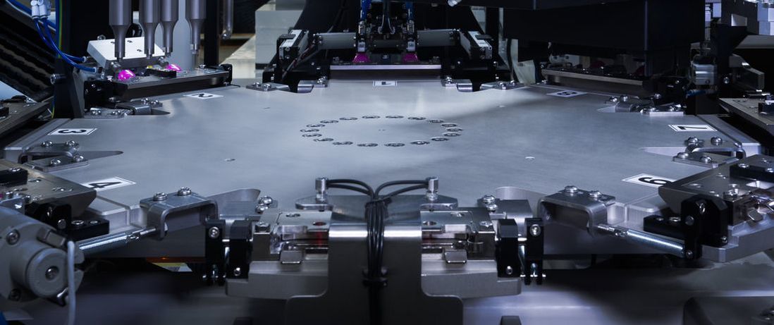
Rotary stages have a single rotary motor that moves the parts from station to station. In this case, there is no dead stroke since the load station comes next after the parts are unloaded.

This rotary stage assembles and inspects lubra plates without any non-utilized strokes.
The flexibility to measure different parts is not trivial, and material handling plays a key role. Both linear and rotary stages can use a common part carrier or nest design, giving manufacturers the flexibility to measure dissimilar parts on the same system. By adjusting the machine vision’s field of view and depth of field, the imaging system can acquire different part features.
The part datum scheme will determine the complexity of the nest design to meet inspection needs. Since the part carrier is an extra component between the part and the nest, manufacturers also need to account for tolerance stacks or the impact on the total tolerance of a part based on assembly challenges. In the linear stage design, the carrier needs to return to load the next part, so there’s also extra handling involved.
Customizing the material handling stage design to overcome manufacturing challenges will ultimately improve product quality.
