With more than 20 million electric vehicles expected to hit the market by 2030, the automotive industry alone is significantly increasing demand for new products and technologies in the battery cell market. This rapid market expansion will present manufacturers with significant challenges, but to overcome these challenges, first we need to identify the critical aspects of battery cell manufacturing.

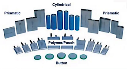
Battery cells come in several form factors, each using very different architectures and chemistry formulations. Even form factors within the same construction geometry can vary significantly, as each one attempts to achieve a higher energy density for more energy storage per package. Though some of the technologies are the same, different battery cells require unique assembly and manufacturing processes, which impacts performance, storage capacity, and the charge/discharge time of the cells.
Beyond battery cell characteristics, automation efforts must consider the manufacturing throughput requirements. Factors that influence these requirements include overall ROI, number of process steps, throughput per cell, conveyance, payload characteristics, system footprint, overall yield, yield per cell, and overall equipment effectiveness. These factors all impact the final cost of the automation solution, driving both the yield and final product quality.
Battery Manufacturing Processes and Assembly Line
Before diving into a closer examination of the project where DWFritz and Bosch partnered, let’s briefly overview a typical cell manufacturing process. As seen in Figure 1, a typical battery cell manufacturing process includes electrode production, cell production, cell module assembly, and battery pack assembly. Within each stage there are several standard steps.
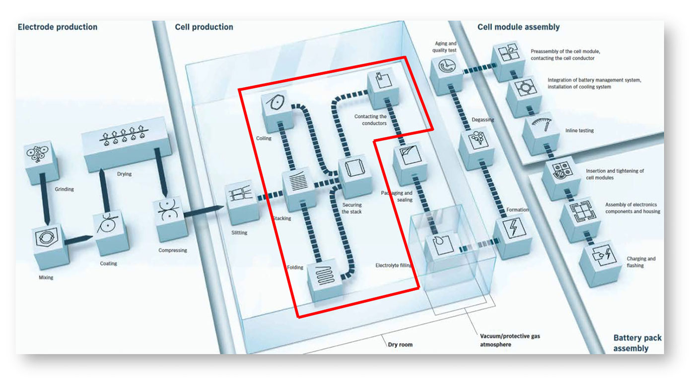
Electrode production includes grinding and preparation of the base materials and mixing, before going on to the coating process for the anodes and cathodes. This is followed by drying, compressing, and slitting to get to the final form factor that you want to go into the actual cell assembly.
Cell production, which is the area highlighted in red in Figure 1 and the focus of this article, involves three different processes the cell can go through for different cell geometries:
- Coiling
- Stacking
- Folding
Once those processes are completed, the cells come back together to be secured into a stable and mechanically sound product. At this point, the busbar will connect the anode and cathode conductors before the cells are packaged and sealed, formed, and degassed in a protective environment, before being tested for quality.
Following the actual cell manufacturing process, the cells move into module assembly, where multiple cells are assembled and interconnected with cooling elements or battery management electronics before final testing. Finally, modules are often assembled into larger battery packs. The modules are mechanically fastened and assembled with some electronics and controls before being charged and again tested for quality.
Developing an Automated Battery Cell Assembly Line
As a result of our partnership with Bosch, we have identified several key process improvements in developing an automated battery cell assembly line. Some of these processes are typical of any cell assembly and production line, regardless of form factors.
Throughput is one of the critical factors to maximizing the overall investment. Achieving the highest possible cycle times requires optimizing the takt times of various process modules, fully utilizing each module, and using line balancing to ensure that we fully maximize all tools.
Assembling the cathode, separator, anodes, and current collectors requires very precise assembly steps, including placement of individual layers, wrapping, or any other interconnected process. As the batteries become smaller and the energy density rises, the tolerances get correspondingly smaller, and drive a lot of the requirements of the assembly tools.
Most of the components are very delicate and must be handled very carefully, particularly the cathode, anode, and separator. Additionally, some of the bus parts are very small and very thin, so they must be carefully handled to prevent damage and maintain quality.
To connect the various components and layers together or facilitate material separation, techniques such as laser welding, thermal gluing, and precision dispensing are used. Precision busbar insertion is used to make the electrical connections between the electrical terminals (anodes and cathodes).
As mentioned earlier, materials used in battery cell production are often delicate and need to be precisely handled. Our designs incorporate precision material handling along with nests, fixtures, and pallets that assist the rapid transfer, movement, and processing of these materials within a process module, and across various modules.
Our system includes in-situ inspection, enabled by high-speed machine vision systems or lasers that perform defect detection, precise material alignment, and high-speed inspection of work-in-progress (WIP) goods. In many instances, camera or laser scans allow for machine vision software to analyze WIP parts using 2D or 3D mapping to help modules determine good vs bad parts. Only good parts are allowed to proceed to the next process step.
Identifying Key Challenges
As you can see from this brief overview, battery manufacturing is a complicated process that is not without significant challenges. But what, exactly, are those challenges? And more importantly, how do we overcome them?
Incoming Material Variability
Variability among incoming material represents a key challenge to battery manufacturing. The incoming materials come from other tools with their own variations and tolerances. The solution here is to develop a strategy to deal with those variations, as well as non-conforming materials, without affecting the throughput.
Incoming material can be defined as raw material inputs (such as a web roll) or material that is transferred across process modules. And incoming materials can have several different types of defects that are characteristic of the previous process step or is a consequence of poor production quality of raw material inputs. An effective system needs to inspect for all possible defects and develop a strategy for the disposition of defective material at the time of introduction or further down the line. Additionally, we need to detect and track quality metrics that are tied back to a particular serial number for quality assessments and traceability down the road.
Tolerances for cathode, anode, and separator components, as well as housing components, are ±50µm or less. Incoming material variability can cause significant issues with achieving these final assembly tolerance requirements, which drives both tight inspection and handling requirements.
Most of the cathode, anode, and separator components arrive on a big roll, requiring roll-to-roll and web handling of very fragile materials. Unwinding the rolls frequently generates static, as well, which must be managed to prevent adverse effects during the assembly process while not damaging or stretching the material.
It must be noted that systems cannot be easily designed to accommodate for a wide variety of incoming material variability without impacting production costs and initial investments. It is therefore essential to ensure a robust quality assurance methodology is in place.
Precision Assembly Tolerances
As previously mentioned, tolerances for battery cell assembly tend to be very tight, with typical cell assembly and alignment tolerances ranging from ±20 to 50µm. Figure 2 illustrates a pouch-type assembly. The alignment between the electrodes, the mechanical housing surrounding it, and the interconnection tolerances can be very tight.
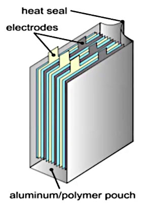
The challenges to achieving these precision assembly tolerances include the previously mentioned material variability, the stack-up and housing tolerance issues among the cathode, anode, and separator components, and, of course, the overall throughput speed required. Maintaining the high level of precision while processing components at increasingly high speed is particularly critical as the overall throughput requirements directly drive the system’s ROI.
Electrical Interconnects
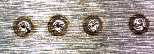
As reliability is critical to both safety and performance of the final cell, electrical interconnects must meet a high-quality standard and present significant challenges. Most of the products include multiple layers, such as a stacked layer or coil, that need to be connected. Generally, these connections are made with a busbar and laser welding, which requires accurately locating the busbar and preparing the material for assembly. For example, if a busbar is coming on a roll, it needs to be straightened and cut. Other times, you may need to insert 50μm-thick substrate onto the cell assembly.
We also frequently must deal with a variety of materials depending on different product configurations and product types. These materials can vary in thickness, material type, and differing mass, but ultimately, whatever the material or configuration, we must ensure good weld quality.
Speed and Throughput
With the growth in battery demand continuing to escalate, the need for higher throughput production has never been higher. Companies continue opening new factories and they are looking for faster equipment – and more of it – to meet the spike in demand. Simply put the challenge here is hitting target cycle time while maintaining both accuracy and repeatability. Customers not only desire higher throughput, but also better ROI and smaller footprint.
While production speeds continue to accelerate, batteries are becoming increasingly smaller with higher energy densities and much tighter tolerances. These demands mean that our cell manufacturing systems are working at the micron level and with typical GRR values of <15%. These requirements present challenges with material handling, inspection, and metrology. Achieving these demanding requirements while maintaining accuracy demands new and innovative approaches to system optimization using controls, vibration, active feedback, and other tools, not to mention business partners, such as DWFritz and Bosch-Rexroth, overcoming such challenges.
Ready to begin?
Flexibility and Scalability
In addition to speed and throughput, flexibility is another big factor in a systems ROI. Any system must be flexible and scalable to meet the requirements of this rapidly evolving market. Cell assembly tools must adapt to changes as new processes develop and throughput requirements change.
Automation systems also must have the capability to rapidly reconfigure the production line for different form factors. From prismatic or cylindrical batteries to pouch and button cells, we design production lines to support different form factors of a cell with minimal changeover time.
Another part of maximizing a tool’s flexibility is allowing seamless communication of system data to anywhere in the world. Modern manufacturing companies employ a global approach, with production facilities spread across countries and even continents. To maximize production efficiency and serviceability, systems must be integrated with an ability to monitor operation of multiple production lines in different geographies.
Manufacturing battery cells is a complex, demanding process with significant challenges. Designing and building a flexible, high-speed system that overcomes these challenges while producing a high-quality product requires a high-level of technical expertise, innovation, and experience. Next, we will look at how DWFritz and Bosch-Rexroth partnered to develop a comprehensive system to meet our client’s needs.
Manufacturing battery cells is a complex, demanding process with significant challenges. Earlier, we highlighted the key challenges in developing a fully automated battery manufacturing line. Now, we look at how DWFritz and Bosch-Rexroth partnered to identify and overcome these challenges and develop a comprehensive system to meet our client’s needs.
Early in the design and planning process, we identified the range of different cell sizes that will be produced so we could design a tool to scale from the smallest to the biggest part expected. To accommodate this range, DWFritz developed the DWFritz Flexible Platform (DFP) 5000. This is a standard assembly module with multiple configurability options. The dual-sided process stations offer flexible, configurable conveyance systems to handle products infeed and return lines, as well as quick-change hardware such as pallets, nests, webs, conveyors, or tray stackers. The DFP 5000 creates a base system within one frame that then allows us to focus on the critical assembly components, such as end-effectors and other modules.
As you can see in Figure 1, our tool included two processes and two buffer/cure stations within one 2×3 meter frame. With the two process stations positioned side-by-side, we could leverage the controls, PLC, kinematics, frame, and electrical distribution across multiple stations. To move the material in and out of the tool, the DFP 5000 was configured with the Bosch Rexroth VarioFlow+ conveyance. The VarioFlow+ conveyor’s compact size facilitated efficient material flow through the various assembly processes and allowed for traffic management within the dense tool.
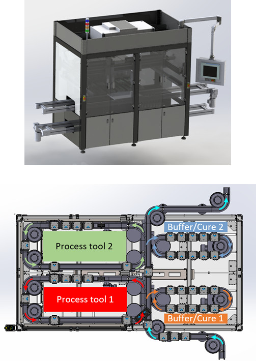
The DFP 5000 uses a precision dowel assembly method for quick change hardware, such as a nest, tooling, or end-effector. In this way, assembling the DFP 5000 does not require mechanical realignment, but rather a simple hardware switch, which optimizes the tool’s uptime and further minimizes the footprint.
Packing a lot of motion into a limited space for web-handling was a significant challenge. To solve this problem, we used Rexroth’s Mi family of smart servo motors with onboard servo drives. As seen in Figure 2, the tool daisy chained multiple Mi motors to significantly reduce cabling and the overall control panel footprint.
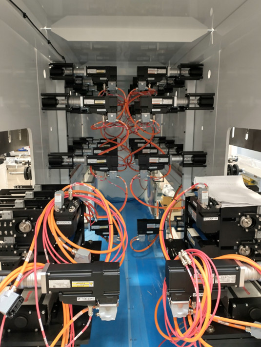
When solving throughput challenges, speed is king. To meet these demands, Rexroth supplied their TS+ pallet conveyance system. Using servo-driven elevators with precise pallet positioning using clamping and lift-and-location mechanisms, the system facilitated a short path, overhead pallet return system to accelerate the pallet return speed, which minimized the number of pallets required. The tight radius of the VarioFlow+ conveyors allowed for very tight snaking turns of the conveyor throughout the assembly processes using diverters and merging to optimize the material flow through the tool. These two systems working in conjunction resulted in a smaller machine footprint.
All of the servo drives and controls use standard open protocols and interfaces for ease of engineering and integration. The main controller uses the latest generation of Rexroth’s controls platform, ctrlX, which affords IoT connectivity via Message Queuing Telemetry Transport (MQTT) protocols to the Manufacturing Execution System (MES) using OPC UA clients and servers and includes expansion options through customer-specific IoT applications. The new platform has a very configurable controller that is very easy to program and includes cloud-based device management via the ctrlX Device Portal, as well as security updates, bug fixes and new function upgrades to improve the controller’s performance over time.
Precision Inspection of Incoming Materials
Everything starts with defect detection of incoming materials, and DWFritz brings years of experience developing our own vision-based inspection systems, algorithms, precision handling, and lighting techniques to detect defects. With such tight assembly tolerances, we leveraged these technologies to enhance the positioning accuracies of our inspection sub-assemblies, and the systems at large. We used machine vision cameras to locate fiducials or datums on the parts so we could perform corrections based on the pick of the part or the incoming assembly.
In the case of web-handling, for example, maintaining precise positions, velocity, and tension control is critical to handling these brittle materials. We used closed-loop sag controls to monitor the web to ensure the proper payout of material across multiple rolls and materials. Bosch-Rexroth high-speed, multi-axis servo drives and motion controllers ensured roll-to-roll or within-roll, cascaded synchronization. Independent rolls were then synchronized to create a more modular material payout that allowed for any number of rolls to be added or removed from the process. This design methodology minimized reconfiguration or reprogramming of the system.
Each material payout roll used optical sensors to perform on-the-fly calculations, measuring the linear speed of the material and performing sag control to accommodate different roll changes with no adverse performance impact on the system. In conjunction with the vision systems, we used high-speed position latching and capture to tell the machine controller where defects are located. The servo-controlled gearing and camming algorithms enabled high-speed material extraction.
Meeting Precision Tolerances Across the Line
To meet the stringent tolerances across various modules, the project considered many parameters. The importance of fixturing, for example, cannot be overstated as precision handling and fixturing go hand in hand. Fixturing using precision kinematic mounts helped in obtaining micron-level repeatability across various modules. We used precision mounts that referenced back to material datums or were designed into the part or the fixtures to help, for instance, laser welding operations or threading operations.
To account for different product types while minimizing changeover and alignment setup time, we used kinematic or precision mounts on the tooling that could be aligned offline and changed over when switching between products.
Bosch-Rexroth supplied various hardware solutions to meet the requirements of this project, including precision linear modules, which have ±5μm repeatability with very precise motion and an XYZ cartesian system used for pick-and-place. Rexroth assembled several different families of high precision linear modules into one solution to meet the requirements of this project, using servo motors with high resolution encoders at ±50 arc-second accuracy. These single cable, single connection solutions feature power and encoder signals on a single cable, reducing the amount of cabling, cost, and complexity of the system. Additionally, servo drives and controllers used advanced tuning algorithms to minimize vibration and settling time, resulting in faster positioning and higher throughputs.
Other options also were considered and used to improve tolerances, including advanced vision systems to both detect parts and for alignment. Figure 3 shows a vision capture of an edge card connector used to locate the pins so we could pick them with high accuracy. If we can detect where we picked the part, then we can remove the part variation for a better assembly tolerance. And, while performing location and alignment, we can also inspect materials. By detecting a part that is bent or misshapen prior to assembly, we could improve yield, and keep the tool running more smoothly throughout the production process.
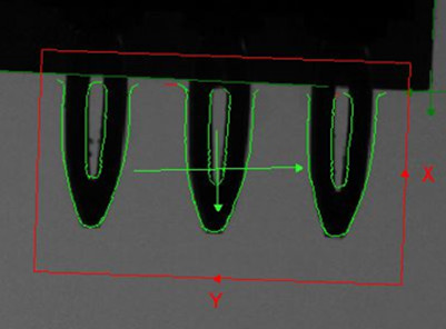
Finally, we used 2D/3D lasers and machine vision systems to perform quality control, checking final assembly at almost every step of the assembly process. As seen in Figure 4, we measured anode to cathode offsets with a 2D laser and matched them with customer specifications to identify defects and send upstream feedback into the assembly process to further tighten up process parameters.
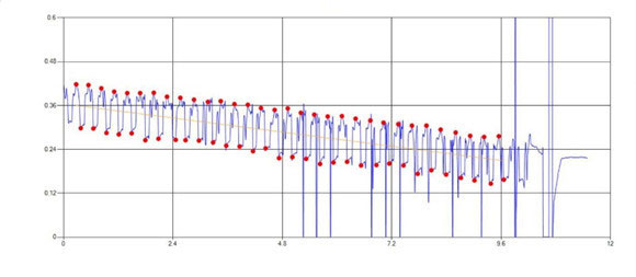
Electrical Interconnections
Electrical interconnects (busbar) that physically connect the various layers of the anode and cathode present significant challenges due to the variety and size of raw materials. To accurately locate the busbar, we again turned to a vision-guided alignment system to locate the busbar and identify where it needed to be on the cell. We then used the same system to locate the exposed electrical interconnections and guide the laser when positioning the welds.
Busbars typically enter the system on a roll and need to be straightened, cut, formed or shaped. We used in-process sensing equipment and quality controls to measure the thickness or width (typically ~50μm-wide soft substrate) and length of the final material. This process needed to be very flexible, accommodating different materials that may vary in thickness, material type, and differing mass while requiring minor adjustments to handle the different busbars.
During welding, we needed to properly position the weld and ensure a good electrical connection. To ensure this outcome, we used mechanisms to clamp multiple layers together for welding to create a zero, or near-zero, gap prior to welding. Leveraging relationships with leading laser vendors and our customer, we outlined specific process parameters and used proven laser settings that produce high quality welds. Finally, in-situ inspection and traceability of the welds confirmed all welds were complete, positioned correctly, and of good quality. The inspection data also was stored and traced back to individual cells via barcodes and incoming material lots to reduce scrap and skip subsequent process steps for non-conforming material.
Throughput and Speed Solutions
To achieve the high speeds and throughputs required by the client, Bosch-Rexroth utilized the XM42 Motion Controller. These high-end motion controllers use CODESYS-based PLC Open Programming, which can be programmed in various languages. A high number of servo motors running on a real-time, deterministic communication bus enables high-speed, synchronized motion. One of the machines featured 54 axes of coordinated motion running from one controller and high-speed motion bus.
To simplify safety and minimize component recovery, integrated network safety modules provide rapid recovery from an operator intervention event (E-Stop) without re-homing of the axis or losing positioning, minimizing the impact and potential scrap. Servo tuning is critical to enable high-speed performance with accuracy and minimal settling time. Together with electronic gearing and camming mechanisms, this affords high-speed punch-out and extraction of web materials.
Key Learnings
The importance of selecting a supplier with a global footprint, the right capabilities, and willingness to collaborate cannot be overstated. Bosch-Rexroth and DWFritz have manufacturing and support facilities all over the globe, and having this extensive footprint becomes increasingly important when installing systems in different countries.
Partners also bring different key capabilities to a project, complimenting each other and filling gaps that might otherwise delay a project or result in substandard outcomes. DWFritz and Bosch Rexroth engineers worked closely together to develop and refine design concepts to improve efficiency and reduce costs on numerous occasions, resulting in more efficient use of modules, reduced system footprint, and lower associated costs.
Collaboration also must extend to your customer. We often talk about Design for Manufacturing (DFX) with customers early in the process, so we can influence subtle process design details, discuss specifications, technologies, and other critical elements that go into designing and manufacturing the final systems. This is critical to developing a seamless, high-performing tool with high yield and high throughput while minimizing costs and meeting your schedule.
In-situ inspections were critical to meet precision assembly requirements across modules and to ensure quality. Tolerances are getting tighter and tighter as we look to hit GR&R levels of 15% or even lower, which require inspection driven by advanced sensors, machine vision algorithms, and innovative lighting. Our years of experience in precision inspection helps us perform these quality inspections at a high level, ensuring that we catch and segregate defects to maximize product quality.
Capturing this defect data also leverages into Industry 4.0, using that inspection information as feedback upstream in the process to improve incoming materials and assembly tools. All of this improves product quality and reduces costs.
Partnering with a supplier with deep application knowledge along with pertinent technical solutions also proved invaluable. Having Rexroth’s engineers and their wealth of expertise in many key areas available to us made this a great partnership.
Finally, the modular design approach provided a key ability to leverage the same hardware for future products and scale. Perhaps we needed to add more stations, change a process station, or change product sizes? By designing this production line for flexibility, it can now be configured and adapted for product changes without the customer needing to purchase all new hardware, which makes it more scalable and able to keep pace with the market.
