Metrology is moving from the lab to the manufacturing line, which brings non-contact techniques, digital twins, and the integrity of point clouds versus discrete measurement data under increased scrutiny. In our last post, we started discussing the Digital Twin. Specifically, we explained the purpose of the Digital Twin, the contact and non-contact methods used to create them, and impact of both data quantity and quality on the integrity of the Digital Twin.
In this post, we’ll delve deeper into the value of big data, look at some examples of tactile and non-contact measurement errors, and finally explore how non-contact measurement techniques can overcome errors through both mathematics and magic.
Data Quality and Measurement Errors
As we previously noted, the common perception is that tactile measurements are more accurate than non-contact, but this is not necessarily true. Each of the methods generates different errors, but the more critical point is how we overcome these errors.
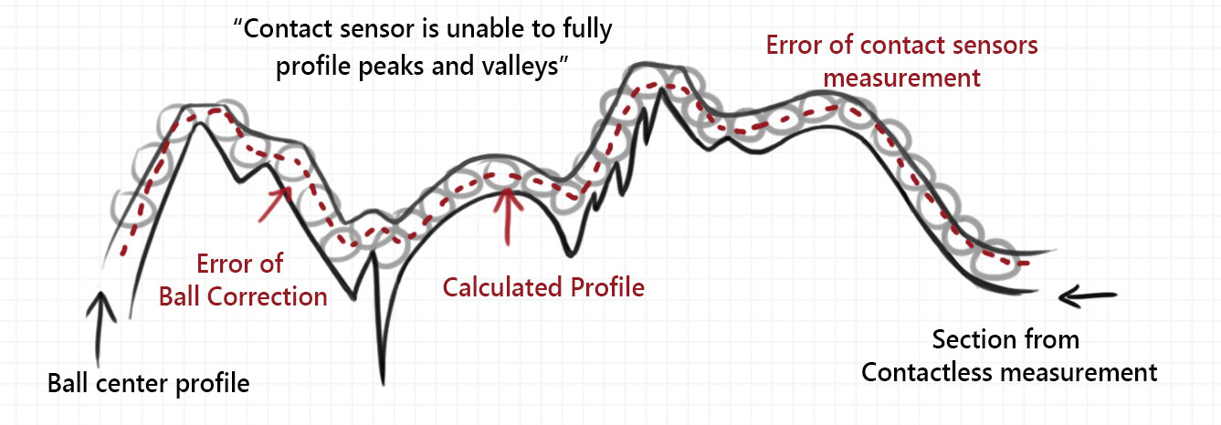
Tactile methods face some common errors, including the Ball Correction Error (see Figure 1) and Hysteresis Error. With probes tips typically in the 2-8mm diameter range, tactile methods capture a small number of discrete measurements, often missing out on data in deeper valleys by riding over the ridges of a surface.
Figure 1. Errors in contact measurement.
On the other hand, non-contact sensors use lasers or WLI, where the a spot size when scanning a surface that is akin to the diameter of probe tip. This spot size is typically in the 3-15µm range, or ~100x smaller than a tactile probe. By way of comparison, think of the diameter of the sun vs the diameter of the earth, where the touch probe is the sun and the non-contact sensor is the earth. As a consequence, non-contact systems overcome issues faced by tactile systems by capturing a point cloud consisting of tens of thousands to millions of data points.
This is not to say that non-contact methods are flawless. These methods also generate errors, just different errors. When gathering all of the data for the point cloud, non-contact sensors have a thickness – commonly referred to as noise. This noise represents the distance of points measured, which is not exactly the same for each data point. Noise can be resolved through two primary methods. One is instrument calibration, which can be quickly performed between scans. The second method is by generating a range of results, rather than a single result, which better offsets the error through data quantity. Non-contact techniques often struggle to measure specular or reflective surfaces. This problem is typically overcome by applying a coating to the surface, reducing reflectivity. By using advanced, high-speed lighting and sensor adjustments, the ZeroTouch® platform does not require any additional coating to measure specular surfaces.
Simply put, both measurement methods generate errors, but non-contact methods have the distinct advantage to overcome them. Just by way of numbers, by capturing a larger quantity of data points (the point cloud), non-contact methods provide a closer representation of the real surface.
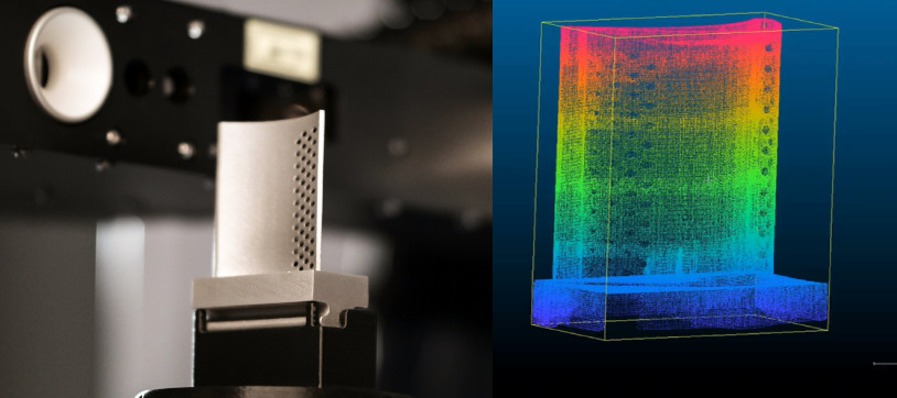
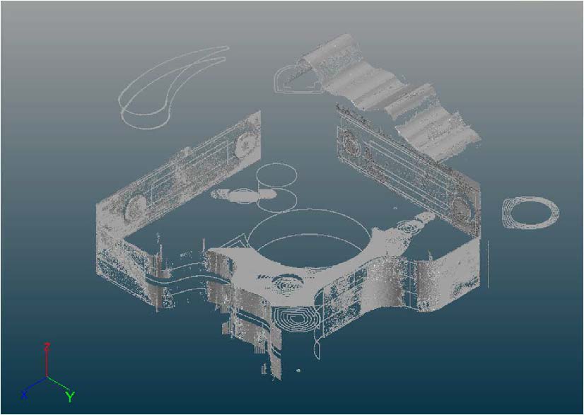
Now let’s look at a real-world example. We analyzed a part with complex features found on parts from several industry verticals. On ZeroTouch, multiple sensors gathered approximately 4 million data points with all CTQs of interest for the part. Each of the generated point clouds were aggregated into the Digital Twin illustrated in Figure 2.
Figure 2. Digital Twin created using non-contact methods.
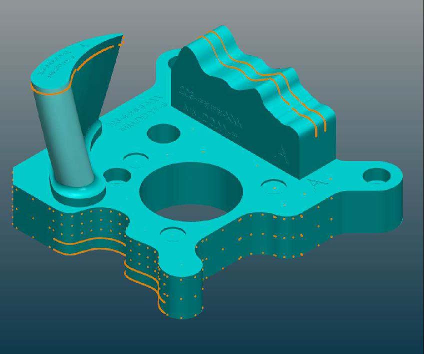
This same part was measured using a tactile method to gather the same CTQs. The tactile method, shown in Figure 3, gathered approximately 1,200 data points and took 14-15mins to complete the scans. In terms of speed, ZeroTouch captured the 4 millions points in ~5mins – nearly 3x faster. This speed and accuracy allows for the integration of metrology and inspection functions directly in to the production line, enabling efficiencies in product quality. Products with complex CTQs can be directly inspected inline. And, the digital twin capabilities enables data to be fed back to the MES and various production systems in real time to improve production efficiencies. For example, if it is observed that the part tolerances are worsening, it could indicate that a tool upstream on the production line needs to be fixed. It could be that a drill bit is wearing out and needs to be replaced. Such a robust feedback system will not only ensure product quality, but reduces waste while also ensuring machine or line up time(s).
Figure 3. Digital Twin created using tactile methods.
The Magic of Big Numbers
Non-contact methods clearly generate a large amount of data – and that’s the point. That’s a very critical component at the heart of the Digital Twin. These big numbers – these point clouds made of up millions of data points – build confidence in the Digital Twin, both in tracking and your confidence level that your Digital Twin is an accurate representation of your entire part.
If we assume two instruments with comparable levels of precision using ISO10360 as a yardstick, , and we look at measuring a section with 100 points, optical sensors offer a single point error impact significantly lower than a tactile single point error. The single point error impact on 100 points (a typical tactile measurement) would have 1/100 the impact of an optical sensor generating 1 million points. The optical sensor single point error impact would be more than 10,000x smaller!
More significantly, the statistical advantage of a point cloud’s big numbers includes the overall measurement error over the entire distribution, which is much smaller than a single point error. The uncertainty decreases as the sample size increases. Simply put, a high-density model is closer representation of the real surface than a low-density model. More is better.


